Mini LED 8x16 board production part 3
Now that the LED bonding is complete, all we have to do is make it shine.
This is an LED driver board using HT16K33 sold by Akizuki Denshi.
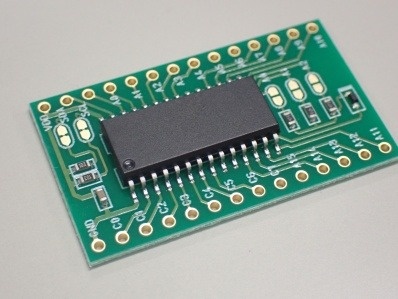
HT16K33 board
The good point is that it is easy to obtain, but even if we look at the specifications, it is not clear how much LED current flows and whether we can set the amount of current. we think this IC is not suitable for proper LED evaluation.
The overall brightness can be changed in 16 steps, but the brightness of each LED cannot be changed.
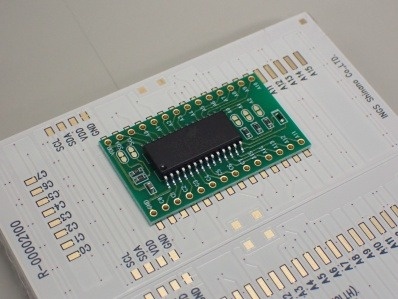
A state where the driver IC board is placed
This board is bonded on the back, which is the board on which the LED is bonded.
In addition, the IC is controlled by I2C, and up to 8 addresses can be set by jumper setting, so up to 8 boards can be moved side by side.
Assuming that they will be moved side by side, the power supply and I2C lines can be easily soldered to the board.
The photo above shows two boards side by side. Adjacent boards can be connected to each other where SCL, SDA, VDD, and GND are written.
First, connect one.
Solder the HT16K33 board and solder it to the I2C of the microcomputer board.
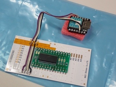
Soldered and connected to the microcomputer
Create a program to turn it on and write it to check the lighting.
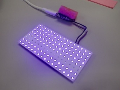
Lighting of mini LED
This IC seems to be used a lot for hobbies, and there are many hints to make it work, so it was easy to move.
In the photo, the third line from the bottom is dark, but due to the relationship between time division drive and shutter speed, the entire surface actually emits light evenly.
Finally, we will line up a lot of these boards and aim for completion using our other technology, "bonding" technology.