Mini LED lighting board part 5
(Continued from last time)
Now that we've bonded it on a PCB, it's time to try bonding it on top of an FPC.
Here are some photos after completion. This is a demo of densely arranged LEDs of one color.
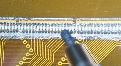
The 0.2 x 0.1 mm mini LED is connected in white.
Since the width of the LED is 0.1 mm and the gap between the LEDs is 0.1 mm, the LEDs are lined up at a pitch of 0.2 mm.
The black one in the photo is the lead of a mechanical pencil (Φ0.5mm). Can you see how small the LED is?
For this demo product, we planned "Let's arrange the LEDs at a pitch of 0.2mm!". The 0.2mm pitch means that even if 100 pieces are lined up, the length is only 20mm. It's hard to come up with an application, but since the purpose is means (bonding technology), we decided to finish it first and then think about it.
The driver IC that controls the LED is IS31FL3743B from Lumissil, the same as the PCB version. The number of lights that can be controlled is as many as 198 lights per chip, which is the reason for selecting SPI control.
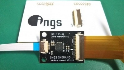
FPC decided to concentrate on LED bonding, and decided to make a separate board for the LED driver.
This is the board we made.
The white board shown in the back is the board used by inserting it into the evaluation board. The evaluation board was used to check the quality of the bonding.
For the board, we designed the circuit and artwork in-house, and asked a PCB manufacturer in China.
To the left of this black board (called a child board) is a 10-pin FFPC. It has a power supply and an SPI bus, and can be controlled by a microcomputer.
The control board is here.
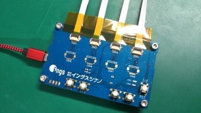
Including the unmounted connector, we tried to connect up to 8 driver ICs.
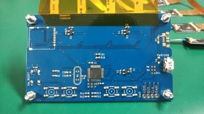
If you look at the photo on the back side, you can see that there are many empty lands. There are many unimplemented functions such as power supply when many LEDs are hung, preparation for data access using SD card, mechanism for USB access, and so on. It is now possible to display the fixed data for the time being, and it has stopped in this state.
There are 5 switches including the reset switch. The SPI bus was for SD card, LED driver, CS (Chip Select) of each driver IC, and GPIO seemed to be needed a lot.
Since it controls a little less than 1600 LEDs with a maximum of 198 x 8 chips, we decided to use ST's 32-bit microcomputer. It is the same STM32F103C8T6 as the evaluation board. As a person in charge of development, we were happy with the familiar ATmega328P, but as part of the technical step-up, we decided to take on the challenge of using this microcomputer for the first time.
(Continued to Part 6)