Mini LED lighting board part 2
Continuing from the previous session.
When we looked into the LED driver IC, it seems that various companies have come out.
Among them, ISSI (currently Lumissil)'s IS31FL3743B was selected for the demo machine. The reasons for choosing it are as follows.
- Up to 198 lights can be controlled with one chip
- An example of an RGB matrix was included in the specifications
- The demo board was likely to be available
- Supports SPI up to 12MHz and seems to move at high speed
- There are few external parts
- High functionality and easy microcomputer control (no real-time processing required)
- It seemed unnecessary to prepare a current limiting resistor for each string
On the other hand, when we assembled the matrix, we were worried that the number would be halfway, 11x6 (xRGB), but it's a technical exhibition. .. ..
Lumissil's website has an evaluation board called IS31FL3743B-QFLS4-EB. We found that we could buy it from some mail order sites by searching with this model number, so we bought it.
That is here.
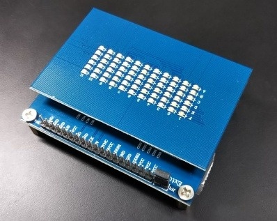
11x6 LEDs in one RGB package are lined up.
The power supply is micro USB, and if you connect it to a mobile battery or a PC, the power will turn on, so you can easily check the lighting.
The switch is on again, and when you press the switch after turning on the power, the demo mode is switched and you can see some displays.
The board is double-decker.
The LED is bonded on the upper part, and the LED driver and the microcomputer for displaying the demo image are mounted on the lower board.
It is a state of the board below.
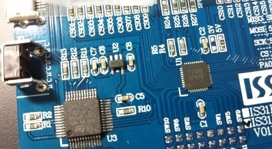
U1 is the LED driver FL31IS3743B, and U3 is the ST 32-bit microcomputer STM32F103C8T6. The circuit diagram is also open to the public, and as long as we look at it, it seems that we can rewrite the firmware of this microcomputer and evaluate it. (In the instruction manual of the IC evaluation board, there was an explanation to connect and control Arduino, but it did not work well, and finally we rewrote the firmware of this STM32 microcomputer)
R5 is the current setting resistor.
The resistance installed as standard is too bright, so we changed it.
The IC evaluation board seemed to be usable as an LED demo board as it was, so we decided to make a replacement for this LED board for the time being.
(Continued to Part 3)