Mini LED lighting board part 6
(Continued from last time)
Now that the control board and FPC have been completed, it's time to bonding the LEDs.
This time we chose the ACF bonding. After pasting the ACF on the FPC, mount the mini LED on the FPC using our mini LED bonder. The mounting accuracy of the bonder is 25um (3σ), and it can be mounted accurately because it is only arranged at equal pitches.
And crimping.
Hold the LED from above with the crimping head.
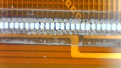
The photo below is the finished product. (Since we took it later, there are a lot of foreign objects, but of course it is more beautiful immediately after completion)

Because it is a small and light LED, it seems that it is pushed during ACF crimping and shifts to the left and right.
Since they are arranged at a 0.2 mm pitch, the intervals are 0.1 mm, but you can see that they are slightly different.
We used our ACF this time, but it seems that it will be necessary to optimize the ACF material and conditions in order to crimp with higher accuracy.
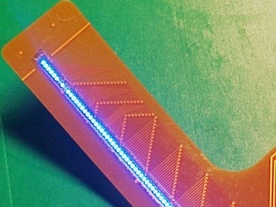
And check the lighting!
Use a relay board to light the evaluation board of the LED driver IC.

However, something that doesn't light up like the photo above. .. ..
It would be nice if we could introduce the details of the cause investigation and countermeasure implementation here, but it is a pity that we cannot introduce it because it is related to know-how.
We didn't quite understand the cause, but once we knew it, it was simple.
Take measures and bonding again.
With just a few FPCs we arranged, we managed to complete the four we had planned.
(Continue)
