(Continued from last time)

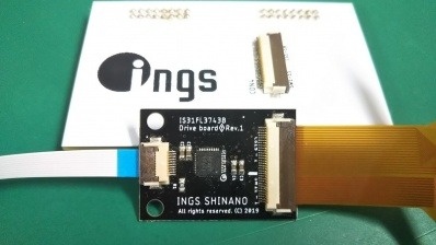
Now that the control board and FPC have been completed, it's time to bonding the LEDs.

This time we chose the ACF bonding. After pasting the ACF on the FPC, mount the mini LED on the FPC using our mini LED bonder. The mounting accuracy of the bonder is 25um (3σ), and it can be mounted accurately because it is only arranged at equal pitches.

And crimping.
Hold the LED from above with the crimping head.

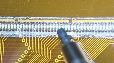
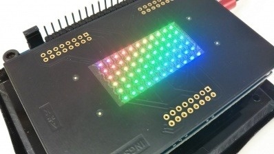
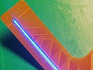
The photo below is the finished product. (Since we took it later, there are a lot of foreign objects, but of course it is more beautiful immediately after completion)


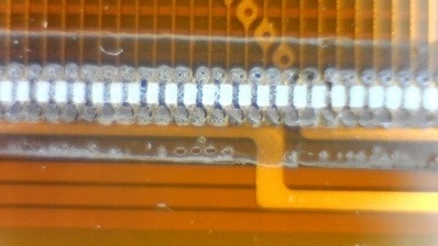
Because it is a small and light LED, it seems that it is pushed during ACF crimping and shifts to the left and right.
Since they are arranged at a 0.2 mm pitch, the intervals are 0.1 mm, but you can see that they are slightly different.

We used our ACF this time, but it seems that it will be necessary to optimize the ACF material and conditions in order to crimp with higher accuracy.

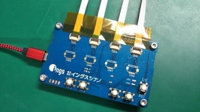
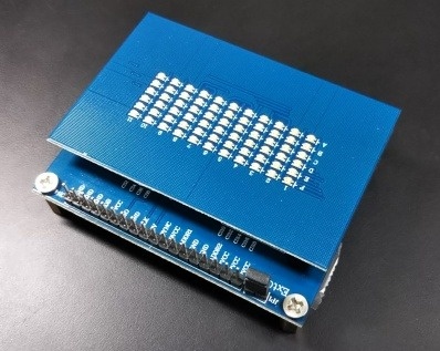
And check the lighting!
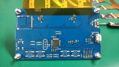
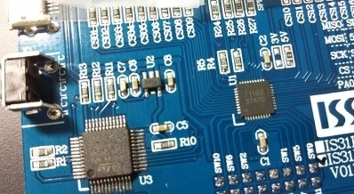
Use a relay board to light the evaluation board of the LED driver IC.


However, something that doesn't light up like the photo above. .. ..

It would be nice if we could introduce the details of the cause investigation and countermeasure implementation here, but it is a pity that we cannot introduce it because it is related to know-how.
We didn't quite understand the cause, but once we knew it, it was simple.

Take measures and bonding again.
With just a few FPCs we arranged, we managed to complete the four we had planned.

(Continue)


(Continued from last time)

Now that we've bonded it on a PCB, it's time to try bonding it on top of an FPC.

Here are some photos after completion. This is a demo of densely arranged LEDs of one color.


The 0.2 x 0.1 mm mini LED is connected in white.

Since the width of the LED is 0.1 mm and the gap between the LEDs is 0.1 mm, the LEDs are lined up at a pitch of 0.2 mm.
The black one in the photo is the lead of a mechanical pencil (Φ0.5mm). Can you see how small the LED is?

For this demo product, we planned "Let's arrange the LEDs at a pitch of 0.2mm!". The 0.2mm pitch means that even if 100 pieces are lined up, the length is only 20mm. It's hard to come up with an application, but since the purpose is means (bonding technology), we decided to finish it first and then think about it.

The driver IC that controls the LED is IS31FL3743B from Lumissil, the same as the PCB version. The number of lights that can be controlled is as many as 198 lights per chip, which is the reason for selecting SPI control.
FPC decided to concentrate on LED bonding, and decided to make a separate board for the LED driver.

This is the board we made.
The white board shown in the back is the board used by inserting it into the evaluation board. The evaluation board was used to check the quality of the bonding.


For the board, we designed the circuit and artwork in-house, and asked a PCB manufacturer in China.

To the left of this black board (called a child board) is a 10-pin FFPC. It has a power supply and an SPI bus, and can be controlled by a microcomputer.
The control board is here.


Including the unmounted connector, we tried to connect up to 8 driver ICs.
If you look at the photo on the back side, you can see that there are many empty lands. There are many unimplemented functions such as power supply when many LEDs are hung, preparation for data access using SD card, mechanism for USB access, and so on. It is now possible to display the fixed data for the time being, and it has stopped in this state.

There are 5 switches including the reset switch. The SPI bus was for SD card, LED driver, CS (Chip Select) of each driver IC, and GPIO seemed to be needed a lot.
Since it controls a little less than 1600 LEDs with a maximum of 198 x 8 chips, we decided to use ST's 32-bit microcomputer. It is the same STM32F103C8T6 as the evaluation board. As a person in charge of development, we were happy with the familiar ATmega328P, but as part of the technical step-up, we decided to take on the challenge of using this microcomputer for the first time.

(Continued to Part 6)


Continuing from the previous session.

The two completed boards can be replaced with the LED boards of Lumissil's evaluation board, so it is completed by replacing them.


For the lighting pattern, we used the one that was included in the evaluation board from the beginning. This is a demo that moves the gradation like the picture.
The color of the entire screen changes, the gradation is applied diagonally as shown in the picture, and several patterns can be switched.
Actually, the company logo is lit up and animated. .. .. we thought, but it seems that 11x6 pixels can not do much, so we are leaving the software that was originally included.

In addition, we have prepared a rewritten firmware of the evaluation board microcomputer (STM32) so that all white lighting, all red lighting, etc. can be performed for evaluation.
Since the evaluation board has a pin header, it can be easily connected to ST-LINK Ver.2.

In the photo above, it looks like 11x6 spots of light are lined up.
In reality, three LEDs, Red, Green, and Blue, are densely arranged at each point. Since RGB are lined up in 0.2 x 0.5 mm, it seems that almost one point is shining to the naked eye. We think it was a demo that clearly shows the features of the mini LED.

Since we were able to bond it on a PCB, we decided to try bonding it on an FPC next.
(Continued to Part 5)


Continuation of the last time.

The following photo shows the completed "Replacement board for the LED matrix board used in the evaluation board for LED driver ICs of Lumissil" (long).


Since it is a part related to know-how, we can not introduce it in detail, but the photo shows the board on which the LED is already bonded.

Since this board and LEDs are lined up with a 0.1 mm width and a 0.1 mm gap, it was very difficult to make the board. Since it was made with a normal FR-4 printed circuit board, the pattern shape that was too thin did not resolve well, and we had to redo it many times. In addition, in the end, the board maker said, "I was originally at the level of refusing, but I received an order by mistake. I made it intentionally, but I want you to forgive me for repeats."
Thanks to this, it was a challenge that the technical team could not afford to fail.
(The second half of this series of posts is an example of a mini LED bonding on an FPC. The FPC tried to form a pattern similar to a PCB, but there were no manufacturing issues.)

Although failure is unacceptable, it is a challenge from setting conditions. The introduced bonder can place the mini LED chip in a fixed place. There are various ways to mechanically fix the LED while making it conductive. In early 2019, we worked on LEDs with a chip size of 0.2x0.38mm. From there, the chip became about half the length and width, and the same conduction method and fixing method could not be used.
After trying various methods, we used the completed 10 PCB boards, and finally all the LEDs turned on in the last 2 boards.

(Continued to Part 4)


Continuing from the previous session.

When we looked into the LED driver IC, it seems that various companies have come out.
Among them, ISSI (currently Lumissil)'s IS31FL3743B was selected for the demo machine. The reasons for choosing it are as follows.

  1. Up to 198 lights can be controlled with one chip
  2. An example of an RGB matrix was included in the specifications
  3. The demo board was likely to be available
  4. Supports SPI up to 12MHz and seems to move at high speed
  5. There are few external parts
  6. High functionality and easy microcomputer control (no real-time processing required)
  7. It seemed unnecessary to prepare a current limiting resistor for each string

On the other hand, when we assembled the matrix, we were worried that the number would be halfway, 11x6 (xRGB), but it's a technical exhibition. .. ..

Lumissil's website has an evaluation board called IS31FL3743B-QFLS4-EB. We found that we could buy it from some mail order sites by searching with this model number, so we bought it.
That is here.


11x6 LEDs in one RGB package are lined up.

The power supply is micro USB, and if you connect it to a mobile battery or a PC, the power will turn on, so you can easily check the lighting.
The switch is on again, and when you press the switch after turning on the power, the demo mode is switched and you can see some displays.

The board is double-decker.

The LED is bonded on the upper part, and the LED driver and the microcomputer for displaying the demo image are mounted on the lower board.

It is a state of the board below.


U1 is the LED driver FL31IS3743B, and U3 is the ST 32-bit microcomputer STM32F103C8T6. The circuit diagram is also open to the public, and as long as we look at it, it seems that we can rewrite the firmware of this microcomputer and evaluate it. (In the instruction manual of the IC evaluation board, there was an explanation to connect and control Arduino, but it did not work well, and finally we rewrote the firmware of this STM32 microcomputer)

R5 is the current setting resistor.
The resistance installed as standard is too bright, so we changed it.

The IC evaluation board seemed to be usable as an LED demo board as it was, so we decided to make a replacement for this LED board for the time being.

(Continued to Part 3)